Monitoring and Controlling of PWM Signal
Monitoring and Controlling of PWM Signal
Monitoring and Controlling of PWM Signal


Overview
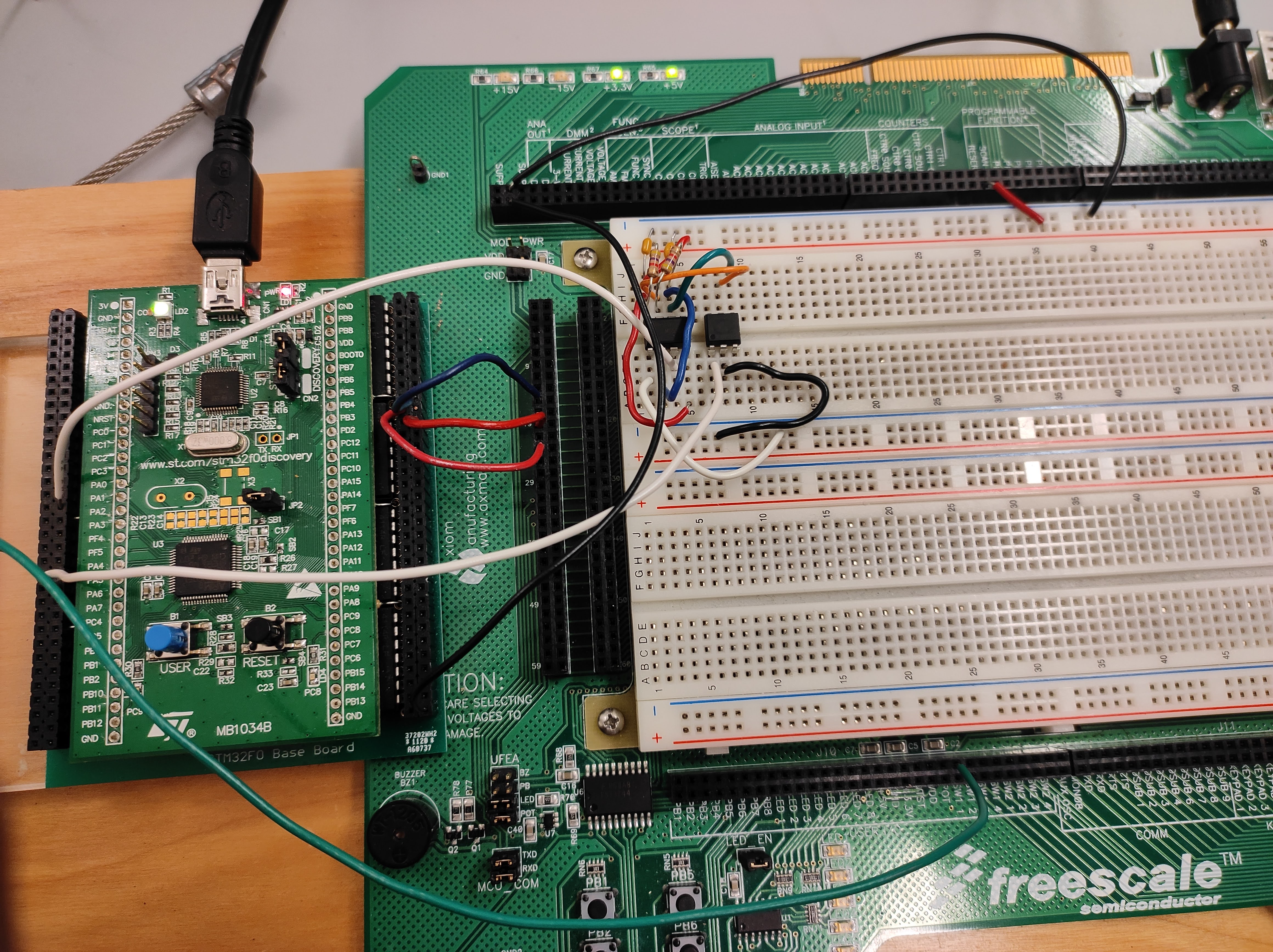
As part of the ECE 355 course, my team and I developed a system to monitor and control a pulse-width-modulated (PWM) signal using an external timer (NE555), an optocoupler (4N35 IC), and an STMF0 Discovery Microcontroller. This project involved integrating various components to generate, measure, and display the PWM signal, providing hands-on experience in microprocessor-based system design and signal processing.
Technical Approach
System Components:
Microcontroller: STMF0 Discovery Microcontroller.
Timer: NE555 Timer to generate the PWM signal.
Optocoupler: 4N35 IC to control the signal frequency.
Analog Components: Potentiometer for adjusting signal parameters.
Display: LCD display on the PBMCUSLK board for showing frequency and resistance values.
Communication: Serial Peripheral Interface (SPI) for data transmission to the LCD.
Development Process:
ADC (Analog to Digital Converter): Configured to read the voltage across the potentiometer on GPIO pin PA5. The ADC was set to continuous mode to provide real-time updates.
DAC (Digital to Analog Converter): Configured to output analog voltages corresponding to the ADC values, driving the 4N35 optocoupler to adjust the PWM signal frequency.
Timer and External Interrupt (TIM2 & EXTI): Used to calculate the frequency of the incoming signal from the NE555 Timer. Configured to handle interrupts and count clock cycles between rising edges.
LCD Control: Managed via SPI communication to display real-time values of resistance and frequency. The LCD was set to 4-bit mode for efficient data handling.
Challenges and Solutions
SPI Communication Initialization:
Challenge: Initializing SPI communication without the
stm32f0xx_spi.cfile referenced in the course materials.Solution: Sourced the required file from an STM32F0-Discovery application template and included it in the project folder, ensuring correct SPI setup.
Signal Accuracy:
Challenge: Ensuring accurate measurement and control of the PWM signal.
Solution: Calibrated the ADC and DAC, and implemented robust interrupt handling for precise frequency calculations.
Potentiometer Sensitivity:
Challenge: Initial small adjustments of the potentiometer did not reflect in the NE555 timer's signal.
Solution: Investigated the forward voltage of the 4N35 optocoupler and adjusted the DAC output values to accommodate it.
Project Outcomes
Current Functionality:
Successfully monitored and controlled a PWM signal using an external NE555 timer and optocoupler, with real-time adjustments via a potentiometer.
Displayed resistance and frequency values on the LCD in real-time, facilitated by SPI communication.
Performance Metrics:
The system effectively measured and displayed frequency changes between 800 Hz and 1300 Hz as the potentiometer resistance varied from 0 to 5000Ω.
Limitations:
Initial small adjustments of the potentiometer did not immediately affect the signal, likely due to the DAC output values needing adjustment for the optocoupler's forward voltage.
Future Improvements
Enhanced Signal Control: Refining the DAC output values to better accommodate the optocoupler's characteristics.
Advanced Display Features: Integrating more complex data visualization on the LCD, such as real-time graphs of signal parameters.
Extended Testing: Conducting extensive testing under varying environmental conditions to ensure system robustness.
Conclusion
The Monitoring and Control of PWM Signal project successfully demonstrated the integration of various components to manage and display a PWM signal. Through hands-on experience with the STMF0 Discovery Microcontroller, NE555 timer, and SPI communication, the project provided valuable insights into embedded systems and signal processing.

