BeepBot – Alarm Clock
BeepBot – Alarm Clock
BeepBot – Alarm Clock


Overview
For my ECE 299 course, we developed BeepBot, a LED-based alarm clock that combines intuitive user interaction with advanced embedded system design. The project aimed to create a functional prototype that allows users to set and control alarms using a simple interface.
Project Goal
The goal was to design an alarm clock that utilizes LED Display, capable of receiving user input via push buttons, and displaying the time. The clock allows users to set the time, configure alarms, snooze, and turn off alarms with ease.
Constraints
Hardware Constraints:
Use of LTC-4727JR 7 Segment 4 Digit display for time display.
STM32F407 Discovery kit as the main processing unit.
A maximum of 6 pushbuttons for user input.
Software Constraints:
Design schematics and PCB layout using KiCAD.
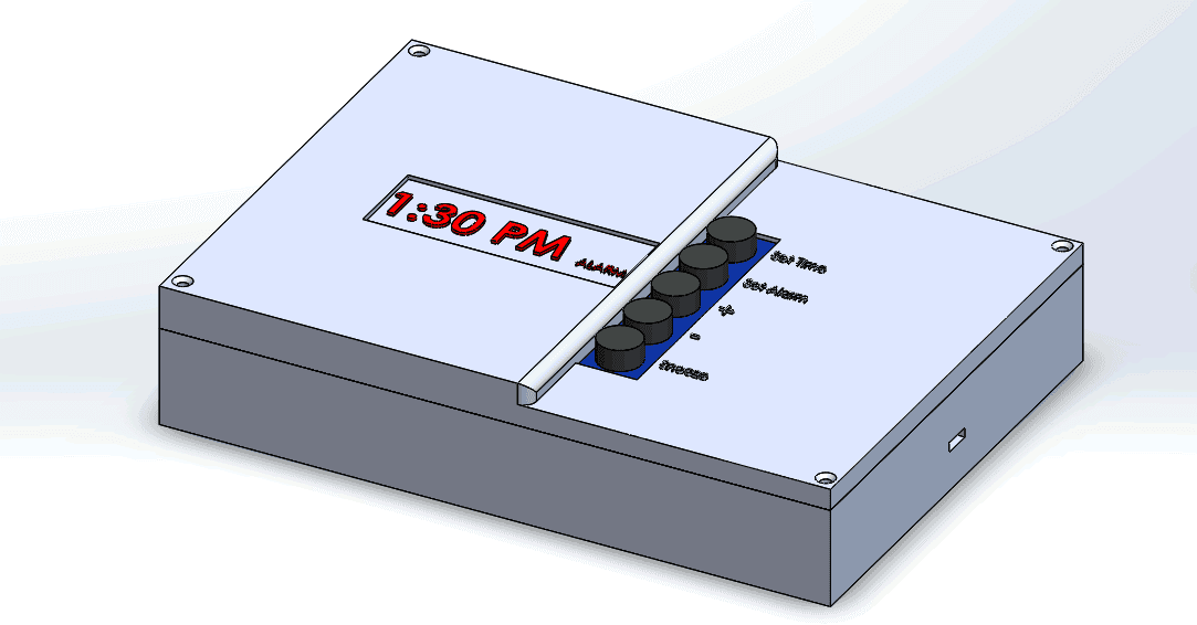
Design the enclosure using SolidWorks.
Program the STM32 board using Eclipse IDE.
Timeline Constraint:
Design, manufacture, and submit the PCB by July 30th.
Requirement Specifications
Electrical Subsystem:
Tactile push button (KSMC615A) for user input.
Resistors and MOSFETs for internal circuit functionality.
Common cathode 4-digit 7-segment display for time display.
Display Subsystem:
7-segment display driven by the STM32 microcontroller.
Rapid sequential switching for a seamless display experience.
Power Subsystem:
ARM 32-bit Cortex M4-CPU microcontroller (STM32F407VG).
Power regulation to ensure safe operation of all components.
Packaging Subsystem:
Plastic enclosure designed in SolidWorks.
User-friendly design ensuring protection and ease of interaction.
Design & Validation
Design Description: The design comprises four main subsystems:
Electrical Subsystem: Houses the main components and interfaces them with the microcontroller.
Display Subsystem: Uses a 4-digit 7-segment display for showing time and alarm status.
Power Subsystem: Regulates and distributes power to all components.
Packaging Subsystem: A protective and user-friendly enclosure designed in SolidWorks.
Design Calculations:
Resistor values calculated to limit current and protect the display.
Power dissipation calculated to ensure safe operation of resistors and other components.
Design Testing:
Conducted virtual tests using TinkerCAD to validate the push-button subsystem and display subsystem.
Successfully simulated the input and display functionality.
Bill of Materials
Key Components:
Tactile push buttons, 150Ω resistors, N-channel MOSFETs, 4-digit 7-segment display, STM32F407VG microcontroller, female connectors, and a lead-free PCB.
Conclusion & Recommendations
Outcome: The BeepBot project successfully met the requirement specifications, with virtual tests confirming the design's validity. Due to COVID-19 restrictions, the physical assembly was not possible, but virtual simulations demonstrated the design's effectiveness.
Future Improvements:
Exclude external pull-up resistors to simplify the design.
Enhance software to include more features and reduce the number of pushbuttons required.
Consider transitioning to an audio-based alarm system for better user interaction.

